Have you ever wondered how computers talk to each other over networks? The Open Systems Interconnection (OSI) model helps explain this complex process. The OSI model breaks down network communication into seven distinct layers, each handling specific tasks that work together to send data from one computer to another. Created by the International Organization for Standardization (ISO), this framework has become a standard way to understand networking.
The OSI model works like a postal system for computer data. When you send an email, your message doesn’t simply jump from your computer to another. It travels down through each layer on your device, across the network, and up through the layers on the receiving device. Each layer adds something important to help your message reach its destination safely.
Understanding the OSI model helps network professionals solve problems faster. When something goes wrong with a network connection, knowing which layer might be causing the issue can save hours of troubleshooting time. The model also provides a common language for network professionals to discuss complex networking concepts.
Image: SVG edition: Gorivero, CC BY-SA 3.0 http://creativecommons.org/licenses/by-sa/3.0/, via Wikimedia Commons
Open Systems Interconnection (OSI) Model Explained: The Foundation of Modern Networking
In the world of computer networking, the Open Systems Interconnection (OSI) Model stands as one of the most fundamental frameworks that help us understand how data travels from one device to another across networks. Whether you’re a student, IT professional, or tech enthusiast, grasping the OSI model is essential for troubleshooting, designing networks, and comprehending how diverse systems communicate seamlessly.
This guide will take you through the OSI model’s seven layers, its historical significance, practical applications, and why it remains relevant in 2025 despite the rise of newer models like TCP/IP.
What Is the OSI Model?
Developed by the International Organization for Standardization (ISO) in the late 1970s and published in 1984, the OSI model is a conceptual framework that standardizes the functions of a telecommunication or computing system into seven distinct layers.
Its purpose is to enable interoperability between different systems and protocols by providing a universal language and structure for network communication.
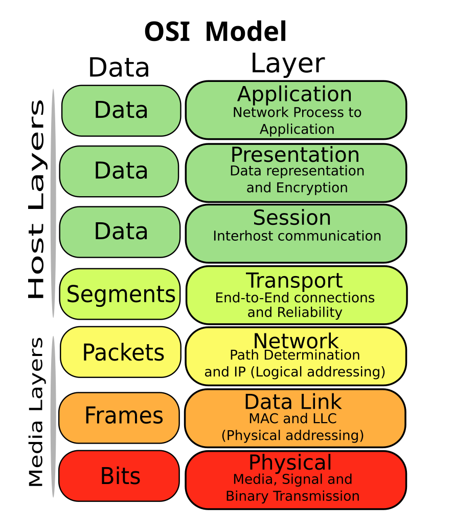
The Seven Layers of the OSI Model
Each layer serves a specific function and communicates with the layers directly above and below it. Here’s a breakdown:
| Layer Number | Layer Name | Primary Function | Examples/Protocols |
|---|---|---|---|
| 7 | Application | Provides network services to end-user applications | HTTP, FTP, SMTP, DNS |
| 6 | Presentation | Translates data formats, encryption, compression | SSL/TLS, JPEG, ASCII |
| 5 | Session | Manages sessions and connections between devices | NetBIOS, SAP |
| 4 | Transport | Ensures reliable data transfer, error recovery | TCP, UDP |
| 3 | Network | Routes data packets across networks | IP, ICMP, IPsec |
| 2 | Data Link | Handles node-to-node data transfer, error detection | Ethernet, PPP, MAC addresses |
| 1 | Physical | Transmits raw bit stream over physical medium | Cables, Hubs, Repeaters, Bluetooth |
Layer-by-Layer Deep Dive
1. Physical Layer
- Deals with the hardware transmission of raw bits over physical media (cables, radio waves).
- Defines electrical signals, data rates, and connectors.
- Example: Ethernet cables, fiber optics, Wi-Fi radio frequencies.
2. Data Link Layer
- Packages raw bits into frames, manages physical addressing (MAC addresses).
- Detects and sometimes corrects errors from the physical layer.
- Divided into two sublayers: Logical Link Control (LLC) and Media Access Control (MAC).
3. Network Layer
- Responsible for routing packets through different networks.
- Uses logical addressing (IP addresses) to determine the best path.
- Handles packet forwarding, fragmentation, and traffic control.
4. Transport Layer
- Provides end-to-end communication control.
- Ensures complete data transfer with error checking and retransmission.
- TCP (Transmission Control Protocol) offers reliable connection; UDP (User Datagram Protocol) offers faster but less reliable communication.
5. Session Layer
- Manages sessions or dialogues between computers.
- Establishes, maintains, and terminates connections.
- Controls data exchange synchronization.
6. Presentation Layer
- Translates data between the network and application formats.
- Handles encryption, compression, and data formatting.
- Ensures that data sent from the application layer of one system is readable by the application layer of another.
7. Application Layer
- Closest to the end user.
- Provides network services directly to applications.
- Examples include web browsers (HTTP), email clients (SMTP), and file transfer programs (FTP).
Why the OSI Model Still Matters in 2025
Though the TCP/IP model is the practical foundation of the modern internet, the OSI model remains invaluable for:
- Education: It provides a clear, structured way to understand complex networking concepts.
- Troubleshooting: Network professionals use the OSI layers to isolate problems — e.g., is the issue at the physical connection, IP routing, or application?
- Protocol Development: Many protocols map to OSI layers, aiding in designing interoperable systems.
- Vendor-Neutral Framework: OSI is not tied to any specific technology or vendor, making it universally applicable.
OSI Model vs TCP/IP Model: What’s the Difference?
| Aspect | OSI Model | TCP/IP Model |
|---|---|---|
| Layers | 7 (Physical to Application) | 4 (Link, Internet, Transport, Application) |
| Origin | Developed by ISO as a theoretical model | Developed by DARPA for ARPANET |
| Usage | Conceptual teaching tool | Practical, real-world protocol suite |
| Layer Functions | Strictly defined, distinct layers | Some layers combine OSI functions |
Real-World Applications of OSI Model
- Network Design: Helps architects design networks with clear separation of concerns.
- Security: Firewall and intrusion detection systems operate at different OSI layers.
- Interoperability Testing: Vendors test devices against OSI standards to ensure compatibility.
- Troubleshooting Tools: Tools like Wireshark analyze traffic by OSI layers to diagnose issues.
Advanced Insights: OSI Model in Modern Technologies
- Cloud Computing: OSI layers guide secure data transmission between cloud services and clients.
- IoT (Internet of Things): Devices often operate at lower OSI layers but rely on upper layers for data formatting and applications.
- 5G Networks: OSI principles underpin the complex multi-layered architecture of 5G communication.
- Cybersecurity: Layered defense strategies map directly to OSI layers, protecting from physical tampering to application-level attacks.
Tips for Mastering the OSI Model
- Visualize with Diagrams: Use layered diagrams to associate protocols and devices with each OSI layer.
- Practice Layer Identification: When analyzing network traffic, identify which layer each protocol or device corresponds to.
- Use Mnemonics: Remember the layers with phrases like “Please Do Not Throw Sausage Pizza Away” (Physical, Data Link, Network, Transport, Session, Presentation, Application).
- Stay Updated: Follow industry trends where OSI concepts are applied, such as SDN (Software Defined Networking) and NFV (Network Function Virtualization).
Key Takeaways
- The OSI model divides network communication into seven layers that work together to send data between devices.
- Each layer has a specific job, from physical connections at the bottom to user applications at the top.
- Network troubleshooting becomes more efficient when problems can be isolated to specific OSI layers.
Overview of the OSI Model
The OSI Model provides a standardized way for different computer systems to communicate over a network. It divides network communication into seven distinct layers, each with specific functions that work together to enable data transfer between devices.
Purpose and Benefits
The OSI Model serves as a reference framework that helps network professionals understand how network communications work. By breaking down complex network interactions into seven manageable layers, it simplifies troubleshooting and system design.
Each layer has a specific job and works with the layers above and below it. This separation of concerns makes it easier to develop new technologies without changing the entire system.
The model also promotes interoperability between different vendors’ products. When manufacturers follow the OSI guidelines, their equipment can work together seamlessly, regardless of who made it.
For network administrators, the OSI Model provides a common language and structure for discussing network issues. This standardization helps teams solve problems more efficiently.
Historical Context
The OSI Model was developed in the late 1970s by the International Organization for Standardization (ISO). It emerged during a time when computer networks were growing rapidly but lacked standardization.
Before the OSI Model, most networks used proprietary protocols that couldn’t easily communicate with systems from different vendors. IBM’s System Network Architecture (SNA) dominated the market, but it wasn’t designed to work with other systems.
The ISO created the OSI Reference Model to address this fragmentation. Published officially in 1984, it aimed to establish a universal standard for network communications.
Though the OSI Model never achieved complete practical implementation, it became an essential educational tool. Today’s networks primarily use the TCP/IP protocol suite, which doesn’t strictly follow the OSI layers but was influenced by similar concepts.
The OSI Model’s lasting impact lies in providing a conceptual framework that continues to guide network design and troubleshooting.
Layer 1: Physical Layer
The Physical Layer forms the foundation of the OSI model, handling the actual transmission of raw bits across physical media. It defines the hardware specifications, electrical signals, and physical connections needed for network communications.
Functions
The Physical Layer converts data into signals for transmission over network media. It manages the binary transmission of 1s and 0s through electrical, light, or radio signals. This layer establishes, maintains, and deactivates physical connections between devices.
Key functions include bit synchronization, which coordinates the sender and receiver timing, and bit rate control, which manages transmission speed. The Physical Layer also handles data encoding, converting bits into signals appropriate for the transmission medium.
The layer defines physical topologies like bus, star, ring, and mesh configurations. It specifies voltage levels, timing of voltage changes, physical data rates, and maximum transmission distances.
Standards and Protocols
Several organizations develop standards for the Physical Layer. The IEEE 802.3 standard defines Ethernet specifications, while IEEE 802.11 covers Wi-Fi technologies. The International Telecommunication Union (ITU) creates standards for telephone networks and cable systems.
Common Physical Layer protocols include:
- RS-232: For serial communication
- USB: For connecting peripherals
- DSL: For high-speed internet over phone lines
- SONET/SDH: For optical fiber networks
These protocols define characteristics such as transmission rates, cable types, connector designs, and signal voltages. They ensure compatibility between network devices from different manufacturers.
Hardware and Media
The Physical Layer works with various hardware components and transmission media. Network interface cards (NICs) serve as the interface between computers and network cables. Repeaters boost signals to extend network reach, while hubs connect multiple devices in a network segment.
Transmission media include:
- Copper cables: Twisted pair (CAT5, CAT6) and coaxial cables
- Fiber optic cables: Using light signals for high-speed, long-distance communication
- Wireless media: Radio waves for Wi-Fi and Bluetooth connections
Each media type offers different advantages in terms of cost, distance capability, and resistance to interference. For example, fiber optic cables provide higher bandwidth and immunity to electromagnetic interference but cost more than copper cables.
Layer 2: Data Link Layer
The Data Link Layer handles the reliable transfer of data between directly connected nodes. It’s divided into two sublayers: MAC and LLC, which together manage error detection, media access control, and flow control for data sent across physical networks.
Media Access Control Sublayer
The Media Access Control (MAC) sublayer serves as the interface between the Logical Link Control sublayer and the physical layer. It controls how devices gain access to the network medium and transmit data.
MAC addresses are 48-bit physical addresses permanently assigned to network interface cards. Unlike IP addresses, MAC addresses are fixed and unique to each device. They’re written as six pairs of hexadecimal digits (for example, 00:1A:2B:3C:4D:5E).
The MAC sublayer also handles:
- Frame formatting: Organizes data into frames with headers and trailers
- Physical addressing: Adds source and destination MAC addresses to frames
- Channel access control: Determines when devices can transmit data on shared networks
This sublayer uses different protocols based on network type, such as CSMA/CD for Ethernet or token passing for Token Ring networks.
Logical Link Control Sublayer
The Logical Link Control (LLC) sublayer sits above the MAC sublayer and provides an interface between the MAC protocols and the Network layer above. It manages communication between devices regardless of their physical connection methods.
The LLC sublayer performs these key functions:
- Flow control: Prevents overwhelm when sending data between nodes of different speeds
- Multiplexing: Allows multiple network protocols to share the same physical connection
- Connection services: Provides connectionless and connection-oriented communication
IEEE 802.2 defines the LLC standard. It supports three types of operation: unacknowledged connectionless service, connection-oriented service, and acknowledged connectionless service.
The LLC uses Service Access Points (SAPs) to identify upper-layer protocols and track multiple connections between devices.
Error Detection and Correction
Error detection and correction are critical functions of the Data Link Layer that ensure data integrity across physical networks. When data travels across physical media, it can become corrupted.
The Data Link Layer uses several techniques to detect errors:
- Parity checking: Adds an extra bit to detect if data was corrupted during transmission
- Cyclic Redundancy Checks (CRC): Uses polynomial division to generate a checksum for detecting changes to raw data
- Checksums: Creates a value based on the data to verify integrity
For correction, the layer may use:
- Automatic Repeat Request (ARQ): Requests retransmission when errors are detected
- Forward Error Correction: Adds enough redundant data to allow the receiver to recover from certain errors without retransmission
These mechanisms ensure reliable delivery by catching transmission errors before data moves up to higher layers of the network stack.
Layer 3: Network Layer
The Network Layer manages the addressing and routing needed to move data packets between different networks. It determines the best path for data to travel and handles logical addressing.
Routing Functions
The Network Layer’s main job is routing data across networks. It decides which path is best for packets to travel from source to destination. This happens through routing tables and protocols that track network conditions.
Routers operate at this layer, examining packet headers to determine where to send data next. They make decisions based on:
- Network congestion
- Hop count (number of routers to pass through)
- Line speed
- Cost of each route
When a packet reaches a router, the device checks its destination address. It then consults its routing table to find the best next hop. This process repeats until the packet reaches its final destination.
IP Protocol
Internet Protocol (IP) is the primary protocol at Layer 3. It provides the addressing system that identifies every device on a network. Two main versions exist today:
- IPv4 – Uses 32-bit addresses (like 192.168.1.1)
- IPv6 – Uses 128-bit addresses to solve IPv4 address exhaustion
IP handles addressing through IP addresses that work like postal codes for data. Each device needs a unique address to send and receive information.
IP is connectionless, meaning it doesn’t establish a dedicated path before sending data. Each packet travels independently, which makes the system flexible but doesn’t guarantee delivery.
IP also handles fragmentation, breaking large data packets into smaller pieces that can travel across networks with different size limits.
Layer 3 Protocols and Services
Several important protocols operate alongside IP at the Network Layer:
ICMP (Internet Control Message Protocol) provides error reporting and diagnostic functions. Ping and traceroute tools use ICMP to test connectivity.
OSPF (Open Shortest Path First) and BGP (Border Gateway Protocol) are routing protocols that help routers share information about network paths and conditions.
Other key services include:
- Network Address Translation (NAT) – Allows multiple devices to share one public IP address
- Quality of Service (QoS) – Prioritizes certain types of traffic
- IPsec – Provides security for IP communications through encryption
These protocols and services work together to ensure data finds its way efficiently across complex networks while maintaining security and performance standards.
Layer 4: Transport Layer
The Transport Layer serves as the crucial connection point between the host and end systems, ensuring complete data transfer across networks. It manages traffic flow, establishes communication protocols, and provides error recovery mechanisms.
TCP and UDP Protocols
The Transport Layer primarily uses two protocols: Transmission Control Protocol (TCP) and User Datagram Protocol (UDP). These protocols serve different purposes based on application needs.
TCP provides reliable communication through a connection-oriented approach. It establishes a connection before data transfer begins, confirms delivery, and ensures data arrives in the correct order. This makes TCP ideal for applications where accuracy is critical, such as web browsing, email, and file transfers.
UDP offers connectionless communication without delivery guarantees. It doesn’t establish connections or verify data arrival, making it faster but less reliable than TCP. Applications that prioritize speed over accuracy—like video streaming, online gaming, and VoIP calls—typically use UDP.
The choice between TCP and UDP depends on whether the application requires reliability or speed.
End-to-End Communication
The Transport Layer creates end-to-end connections between source and destination devices across networks. This layer masks the complexities of network infrastructure from applications.
It handles addressing through ports—numerical identifiers that direct data to specific applications. Common examples include port 80 for HTTP web traffic and port 443 for HTTPS secure communications.
This layer also manages segmentation and reassembly of data. Large messages are broken into smaller segments before transmission and reassembled at the destination. Each segment contains sequence numbers to maintain proper order.
The Transport Layer effectively creates a logical connection between applications running on different devices, regardless of the physical network structure between them.
Error Recovery and Flow Control
The Transport Layer implements mechanisms to handle transmission problems and manage data flow between devices.
Error Recovery: TCP provides error detection and correction through acknowledgments and retransmissions. When segments are lost or corrupted, the receiver requests retransmission. This ensures data integrity even on unreliable networks.
Flow Control: This prevents senders from overwhelming receivers with too much data. TCP uses a sliding window technique to adjust transmission rates based on receiver capacity.
Congestion Control: The Transport Layer monitors network congestion and adjusts data transmission rates accordingly. This prevents network overload and helps maintain overall performance.
These mechanisms work together to provide reliable communication despite network limitations. While UDP lacks these features, TCP’s comprehensive error recovery and flow control make it suitable for applications requiring data integrity.
Layer 5: Session Layer
The Session Layer manages connections between applications on different devices. It sets up, maintains, and ends communication sessions, ensuring data moves smoothly between applications regardless of how long the exchange takes.
Session Establishment
The Session Layer creates pathways for data to travel between devices. When you start a video call or log into a remote server, this layer establishes the connection. It assigns unique identifiers to each session so your computer can handle multiple connections at once without mixing them up.
This layer uses protocols like NetBIOS and RPC (Remote Procedure Call) to start these connections. During setup, devices agree on communication rules—who sends data first, how they’ll take turns talking, and what happens if something goes wrong.
Session establishment includes authentication steps to verify who’s connecting. This helps prevent unauthorized access to systems and ensures you’re communicating with the right device.
Session Termination
When communication ends, the Session Layer properly closes connections to free up system resources. This process involves sending signals between devices indicating they’re ready to disconnect.
Proper termination prevents data loss by ensuring all information transfers before closing. If a video call ends abruptly, this layer works to save any data in transit and close connections cleanly.
Some protocols use specific termination signals like “FIN” in TCP. Others implement timeout mechanisms that close inactive sessions automatically.
The termination process also includes status updates. Devices exchange information about whether the session ended successfully or encountered problems, helping applications respond appropriately.
Communication Coordination
The Session Layer coordinates how data flows during a session. It creates checkpoints called synchronization points that mark important stages in communication.
If a connection breaks, these checkpoints let devices resume from where they left off instead of starting over. This is especially useful for large file transfers or lengthy database operations.
The Network File System (NFS) relies on these coordination features. When accessing remote files, NFS uses session management to maintain connections even through brief network issues.
This layer also handles dialog control—determining which device can transmit data and when. It supports:
- Simplex: One-way communication
- Half-duplex: Two-way but one direction at a time
- Full-duplex: Two-way simultaneous communication
For video conferences, this coordination ensures everyone can speak and be heard at the appropriate times without data collisions.
Layer 6: Presentation Layer
The Presentation Layer works as a translator between the Application Layer and the network, handling how data is formatted, encrypted, and converted between different systems. It ensures that information sent from one system can be read properly by the receiving system.
Data Formatting
The Presentation Layer converts data from the application into a standard format that can be transmitted over the network. It handles different data formats and structures to ensure compatibility between systems.
When you save a file on your computer, this layer might convert it from the format your application uses to a standard format for network transmission. For example, it can convert data between ASCII and EBCDIC character encoding systems.
The layer also manages data compression to reduce the size of transmitted information. This helps save bandwidth and makes data transfer faster. Common compression methods include ZIP, JPEG for images, and MPEG for video files.
Encryption and Decryption
Security is a key function of the Presentation Layer. It handles encryption of data before transmission and decryption when data is received.
When you connect to a secure website (HTTPS), the Presentation Layer encrypts your information before sending it. This prevents unauthorized users from reading sensitive data like passwords or credit card numbers.
Common encryption protocols include:
- SSL/TLS: Used for secure web browsing
- SSH: For secure remote connections
- PGP: For encrypted email
The layer ensures that even if someone intercepts your data, they cannot understand it without the proper decryption keys.
Character Code Translation
Different computer systems use different ways to represent text characters. The Presentation Layer translates between these different character encoding systems.
For instance, when sending text between a Windows computer and a Mac, this layer converts between the different character sets each system uses. Common character encoding systems include:
- ASCII: Basic English characters
- Unicode/UTF-8: Supports characters from virtually all languages
- EBCDIC: Used mainly on IBM mainframes
This translation ensures that text appears correctly on the receiving system. Without it, special characters might display as strange symbols or cause errors in applications.
The layer also handles syntax conversion when different systems use different ways to structure data.
Layer 7: Application Layer
The Application Layer is the top layer of the OSI model and directly interacts with end users. It provides network services to applications and enables users to access network resources.
Network Process to Application
The Application Layer connects user applications to network services. When you browse websites, check email, or use file sharing programs, this layer handles the communication between your software and the network.
Common protocols at this layer include HTTP for web browsing, SMTP for sending emails, and DNS for translating domain names into IP addresses. For example, when you type “www.example.com” in your browser, DNS protocol works within the Application Layer to find the actual IP address of that website.
Web browsers operate at this layer, providing a user interface to access and display web content. They interpret HTML, CSS, and JavaScript to render websites properly on your screen.
File Transfer and Management
The Application Layer handles moving files between devices on a network. FTP (File Transfer Protocol) is a key protocol here, allowing users to upload, download, and manage files on remote servers.
Other important protocols include TFTP (Trivial File Transfer Protocol) for simpler transfers and SFTP (Secure File Transfer Protocol) for encrypted file transfers. These protocols define rules for:
- Uploading files to servers
- Downloading files from servers
- Organizing folders and directories
- Setting file permissions
Many cloud storage services use Application Layer protocols to sync files across devices. When you save a document to a cloud drive, this layer manages the transfer process.
Mail Services
Email systems rely heavily on the Application Layer for sending, receiving, and managing messages. Several key protocols work together to make email possible:
- SMTP (Simple Mail Transfer Protocol): Handles sending emails between servers
- POP3 (Post Office Protocol): Retrieves emails from servers to local devices
- IMAP (Internet Message Access Protocol): Manages emails while keeping them on the server
When you send an email, your mail client uses these protocols to properly format the message, add attachments, and route it to the recipient’s mail server. The Application Layer also handles features like email filtering, sorting, and searching.
Email security features like spam filtering and encryption also operate at this layer, protecting users from malicious messages and keeping sensitive information private.
OSI Model and Network Security
The OSI model provides a framework for understanding how network security can be implemented at different layers. Each layer requires specific security measures to protect data as it travels across networks.
Security at Different Layers
Network security must be considered at every OSI layer. At the Physical layer, security focuses on protecting hardware from unauthorized access and environmental threats. This includes locks on server rooms, surveillance cameras, and proper cable management.
The Data Link layer uses MAC address filtering and IEEE 802.1X for access control. This helps prevent unauthorized devices from connecting to the network.
Network Layer security implements firewalls and IPsec protocols. These tools filter traffic based on IP addresses and encrypt data packets during transmission.
The Transport Layer uses TLS/SSL protocols to secure connections. These protocols verify the identity of communicating parties and encrypt data during transmission.
Session and Presentation Layers manage authentication and data formatting respectively. They ensure users are who they claim to be and that data is properly encrypted.
Application Layer Security
Application Layer security is often the most visible to users. This includes authentication methods like passwords, biometrics, and multi-factor authentication to verify user identities.
HTTPS, which uses TLS/SSL, secures web browsing by encrypting communications between browsers and websites. This prevents eavesdropping and man-in-the-middle attacks.
Email security protocols like S/MIME and PGP encrypt messages to protect sensitive information. They also provide digital signatures to verify sender identity.
API security measures protect web services using OAuth, API keys, and rate limiting. These tools control access to resources and prevent abuse.
Application firewalls inspect traffic at this layer to block malicious requests before they reach vulnerable applications. They can identify and stop attacks that might bypass lower-layer security measures.
The OSI Model and TCP/IP
The OSI Model and TCP/IP are fundamental frameworks that guide how networks communicate. While they share similar purposes, they differ in their layer structure and practical implementation in modern networks.
Comparing OSI and TCP/IP Models
The OSI Model contains seven distinct layers: Physical, Data Link, Network, Transport, Session, Presentation, and Application. TCP/IP, also known as the Internet Protocol Suite, uses only four layers: Network Interface, Internet, Transport, and Application.
TCP/IP’s simpler structure combines several OSI functions. For example, TCP/IP’s Application layer handles the functions of OSI’s Application, Presentation, and Session layers. This condensed approach made TCP/IP more practical for real-world implementation.
The Network layer in OSI corresponds to TCP/IP’s Internet layer, where IP (Internet Protocol) operates. Both handle routing data between networks, but TCP/IP was specifically designed for internet connectivity.
Integration and Differences
The main difference between these models is their origin and purpose. The OSI Model was created as a theoretical framework for standardization. TCP/IP developed from practical networking needs and became the foundation of the internet.
OSI is more detailed but rarely implemented exactly as designed. TCP/IP is less detailed but widely implemented in real networks worldwide.
| Feature | OSI Model | TCP/IP Model |
|---|---|---|
| Layers | 7 layers | 4 layers |
| Development | Theoretical first | Practical first |
| Flexibility | More rigid | More flexible |
| Implementation | Less common | Universal |
Another key difference is that protocols were developed after the OSI Model, while TCP/IP protocols were created first, and the model followed.
TCP/IP Protocol Suite
The TCP/IP Protocol Suite contains several important protocols that power today’s internet:
- TCP (Transmission Control Protocol) provides reliable, ordered delivery of data packets
- IP (Internet Protocol) handles addressing and routing packets across networks
- HTTP/HTTPS manages web page requests and responses
- FTP enables file transfers between computers
- SMTP handles email transmission
These protocols work together across TCP/IP’s four layers. For example, when you load a website, HTTP operates at the Application layer, TCP at the Transport layer, IP at the Internet layer, and your network card handles the Network Interface layer.
TCP/IP’s practical design helped it become the standard for internet communication, even though the OSI Model offers a more detailed theoretical framework.
Implementing OSI in Networking Devices
Real-world networking devices implement different layers of the OSI model to perform their specific functions. Each device type specializes in handling particular layers to efficiently move data across networks.
Routers and Switches
Routers operate primarily at the Network Layer (Layer 3) of the OSI model. They make decisions about where to send data packets based on logical addresses like IP addresses. Routers connect different networks together and determine the best path for data to travel.
Switches work at the Data Link Layer (Layer 2). They use MAC addresses to forward data to the correct device within a local network. Unlike basic hubs that simply repeat signals, switches create direct connections between devices.
Modern enterprise routers and switches are often multilayer devices. A multilayer switch can perform both Layer 2 switching and Layer 3 routing functions. This helps reduce network bottlenecks and improves overall performance.
Network Interface Cards
Network Interface Cards (NICs) implement the Physical and Data Link Layers (Layers 1 and 2). Every PC and network device contains at least one NIC to connect to networks.
NICs handle several critical functions:
- Converting data into electrical, radio, or optical signals at Layer 1
- Managing the physical connection to the network
- Processing MAC addresses at Layer 2
- Controlling data flow between the device and network
Modern NICs often offload processing tasks from the computer’s CPU. This includes checksum calculation, encryption, and packet filtering. These features improve network performance while reducing the load on the main system processor.
Bridges and Repeaters
Repeaters work exclusively at the Physical Layer (Layer 1). They receive weak signals, amplify them, and retransmit them at full strength. This extends network range without processing the actual data being transmitted.
Bridges operate at the Data Link Layer (Layer 2). They connect separate network segments while filtering traffic based on MAC addresses. Unlike switches that create direct connections, bridges forward all traffic to connected segments.
Both devices solve specific network problems:
- Repeaters overcome distance limitations of cable types
- Bridges reduce network congestion by blocking unnecessary traffic between segments
While modern networks often replace standalone bridges and repeaters with integrated switch functionality, understanding their role helps explain how OSI principles apply to network design and troubleshooting.
Frequently Asked Questions
The OSI model organizes network functions into seven layers, each with specific roles in data transmission. Understanding these layers helps network professionals troubleshoot issues and design efficient systems.
What are the distinct functions of each layer in the OSI model?
The Physical layer (Layer 1) handles the transmission of raw bit streams over physical media like cables. It deals with electrical signals, cables, and hardware.
The Data Link layer (Layer 2) provides node-to-node data transfer and error detection. It manages MAC addresses and organizes data into frames.
The Network layer (Layer 3) manages routing and forwarding of data packets between different networks. IP addressing happens at this layer.
The Transport layer (Layer 4) ensures complete data transfer and handles flow control. TCP and UDP protocols operate here.
The Session layer (Layer 5) establishes, maintains, and ends connections between applications. It handles session checkpointing and recovery.
The Presentation layer (Layer 6) translates data between the application and the network format. It handles encryption, compression, and format conversion.
The Application layer (Layer 7) provides network services directly to user applications. Web browsers, email clients, and other applications interface at this layer.
How does the OSI model differ from the TCP/IP model in network design?
The OSI model has seven layers while TCP/IP has only four layers. TCP/IP combines the OSI Application, Presentation, and Session layers into one Application layer.
TCP/IP’s Network Interface layer combines the OSI Physical and Data Link layers. This makes TCP/IP more practical for real-world implementation.
The OSI model is conceptual and theoretical, while TCP/IP was created for actual network implementations. Most modern networks use TCP/IP protocols.
TCP/IP protocols evolved before the OSI model was developed, so they don’t perfectly match the OSI layers. This can create some confusion when mapping concepts between models.
Can you explain the role of the Presentation layer within the OSI framework?
The Presentation layer (Layer 6) serves as a translator between the Application and Session layers. It converts data from application format to network format and back.
This layer handles data encryption and decryption for secure transmission. It also manages data compression to improve transmission efficiency.
Format conversion happens here, enabling different systems to communicate. For example, it might convert between ASCII and EBCDIC character sets.
The Presentation layer ensures data from the sending device can be read by the application on the receiving device. It’s sometimes called the “syntax layer” because it manages data syntax.
What is the importance of understanding the OSI model for networking professionals?
The OSI model provides a common language for discussing network issues. Technicians can pinpoint problems to specific layers, making troubleshooting more efficient.
Network professionals use the model to understand complex network operations. Breaking networking into distinct layers makes it easier to learn and teach networking concepts.
The model helps in designing network architecture by defining clear boundaries between functions. This modular approach allows improvements to one layer without affecting others.
Understanding the OSI model helps professionals work with different network technologies and protocols. It creates a framework for comparing and integrating diverse systems.
How do the layers of the OSI model interact during data communication processes?
Data travels down the OSI layers on the sending device and up the layers on the receiving device. Each layer adds or removes its own header information during this process.
The sending device’s Application layer creates data that passes through each lower layer. Each layer adds its own control information (encapsulation) before passing it down.
Physical transmission occurs only at the Physical layer. Data travels as electrical signals, light pulses, or radio waves to the receiving device.
The receiving device’s Physical layer captures the signal and passes data upward. Each layer reads and removes its corresponding header information (de-encapsulation) before passing it up.
What are some common practical applications of the OSI model in networking?
Network troubleshooting relies heavily on the OSI model. Technicians identify which layer contains the problem based on symptoms, allowing for focused solutions.
Network equipment design follows OSI principles. Switches typically operate at Layer 2, routers at Layer 3, and firewalls often function at Layers 3 and 4.
Security implementations map to specific OSI layers. For example, SSL/TLS encryption works at Layers 5-7, while IPsec operates at Layer 3.
Software development for networking applications uses the model to determine which protocols to implement. Developers can focus on the layers relevant to their application.